Automotive Fan Controller
2026-04-20
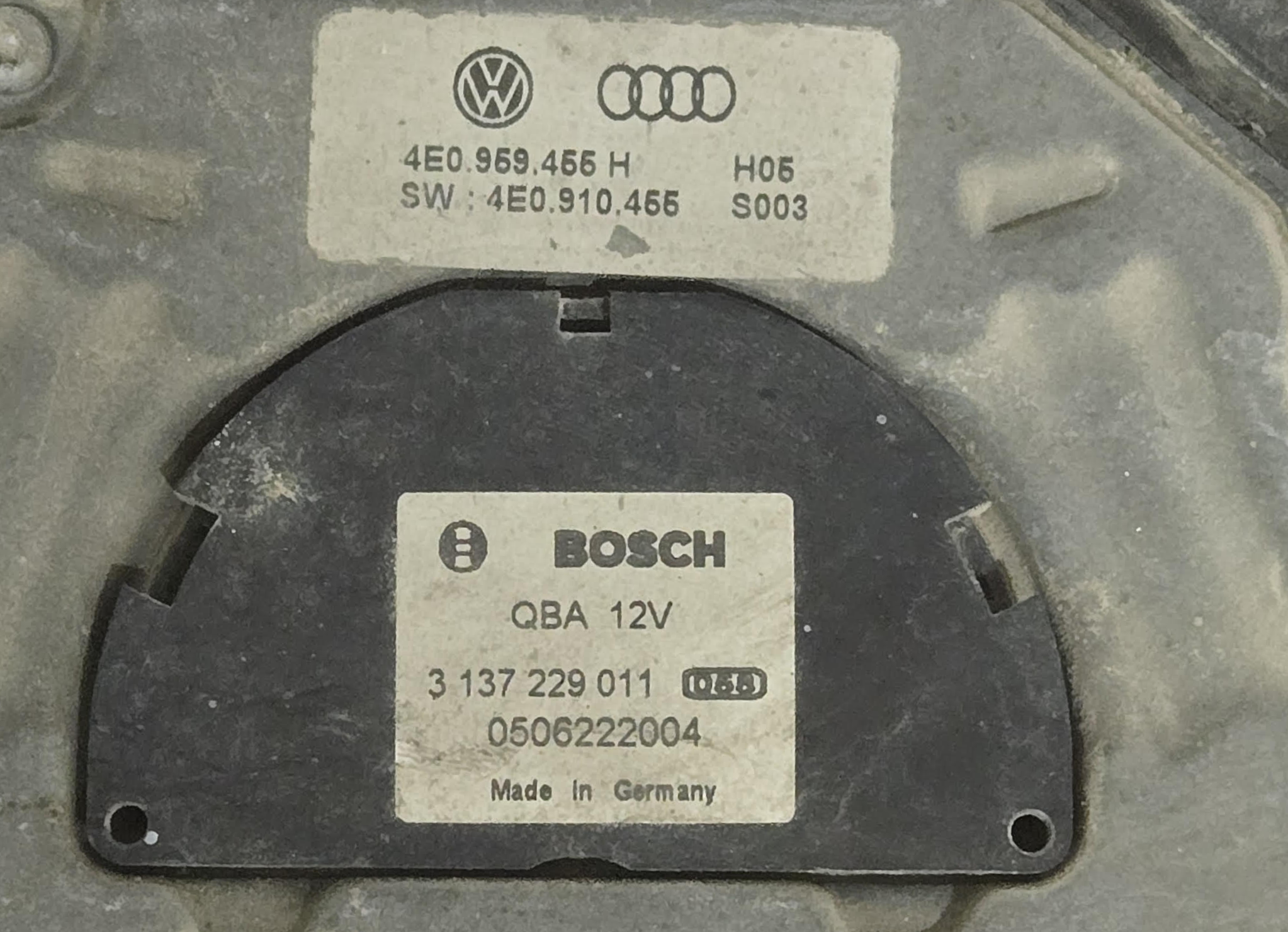
I have Bosch 1-137-328-163 ( Specifically Audi A8 ) Radiator fan and i was wondering if i could use it to swap the noisy clutch fan with it and i want to make it modular so i could swap into any car.
Research
i couldn’t find any documentation or anything related to the fan and how the control signal get sent, also i didn’t have the fan connected to the car, if i had it would’ve been so much easier by reading the control signal using an oscilloscope, so i opted to another method what i did was identifying the cables i there were two thick cables so it safe to assume those are power and ground and two thin cables.
- +12V (Black / Red)
- GND (Brown)
- Signal? (Yellow / Cyan)
- Signal? (Red/Yellow)
the (Yellow / Cyan) cable was pulled high +12v so i assumed it is Signal cable, now comes the part where i have to check if they are using some kind of proprietary communication protocol or maybe CAN Bus and Cable 3/4 are differential pair but cable for is LOW so it cant be CAN Bus, i digged a little deeper in forms and wikis until i encountered w220 wiki which contains page explaining fan motor control for the Mercedes w220 the pinout for the similar fan was available
- +12V (Black / Red)
- GND (Brown)
- PWM? (Yellow / Cyan)
- Ignition? (Red/Yellow)
i tried pulling the ignition high it seems the fan resort into fail safe mode or something after 10 seconds and ramp to full-speed.
subsequently i tried pulling down the PWM cable which did absolutely nothing. for testing and experimenting i took the fan indoors and used ATX PSU with 20A fuse on the 12v rail which surprisingly deliver enough current without blowing the fuse even at the current rush moment.
right after that i made test bench with the RP2040 Dev-Board with serial communication i to be able to adjust Duty Cycle , Counter, Clock Divider during runtime, i did start brute forcing to find the PWM frequency at 50% duty, it took me a while because i started from 100hz until 25khz, the fan just spin at full speed, but i figured that it could be lower than 100hz and it was lower specifically 25hz.
Firmware Design
so i started designing the firmware on the STM32F1 for testing right after that i switched to the STM32G030 Because the STM32F1 is too overkill for the job and more expansive.
Peripherals Mapping
| Peripheral | Purpose |
|---|---|
| ADC1 | NTC Temp Measurement |
| TIM2 | PWM generation (fan control output) |
| TIM1 | Timing base |
| GPIO | Status LED + control signals |
| RCC | External HSE clock configuration |
| I didn’t use External HSE in the PCB design because the PWM signal frequency is very low and it is very unlikely the drift from ISE will cause any significant impact. |
Pin Mapping
| Pin | Function | Description |
|---|---|---|
| PA8 | TIM2_CH1 | PWM output to fan module |
| PA1 | ADC1_IN1 | NTC temperature input |
| PA0 | GPIO_Input | AC signal |
| PC13 | GPIO_Output | Status LED |
| Pin mapping was to make it as easy as possible to write as im using the TSSOP-20 package of the STM32G030F6P6 and for more details you can find the source code at my account GitHub |
$ tags: [embedded] [c] [stm32] [uart]